Steam Page
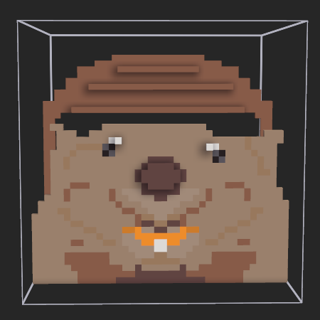
This blogpost describes the approach I take in Outpost Engineer to apply voxel based textures to marching cube meshes.
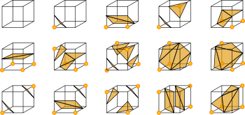
Marching Cubes is an algorithm that can create a smooth 3D model from a set of voxels. Fully explaining marching cubes or voxels is not part of this blogpost, but wikipedia has more information on it.
Some important observations on the algorithm however:
My solution is to blend the 3 (possible) voxel textures corresponding to the three points of a triangle using barycentric coordinates.
Again, wikipedia explains it better, but in essence these are some important takeways:
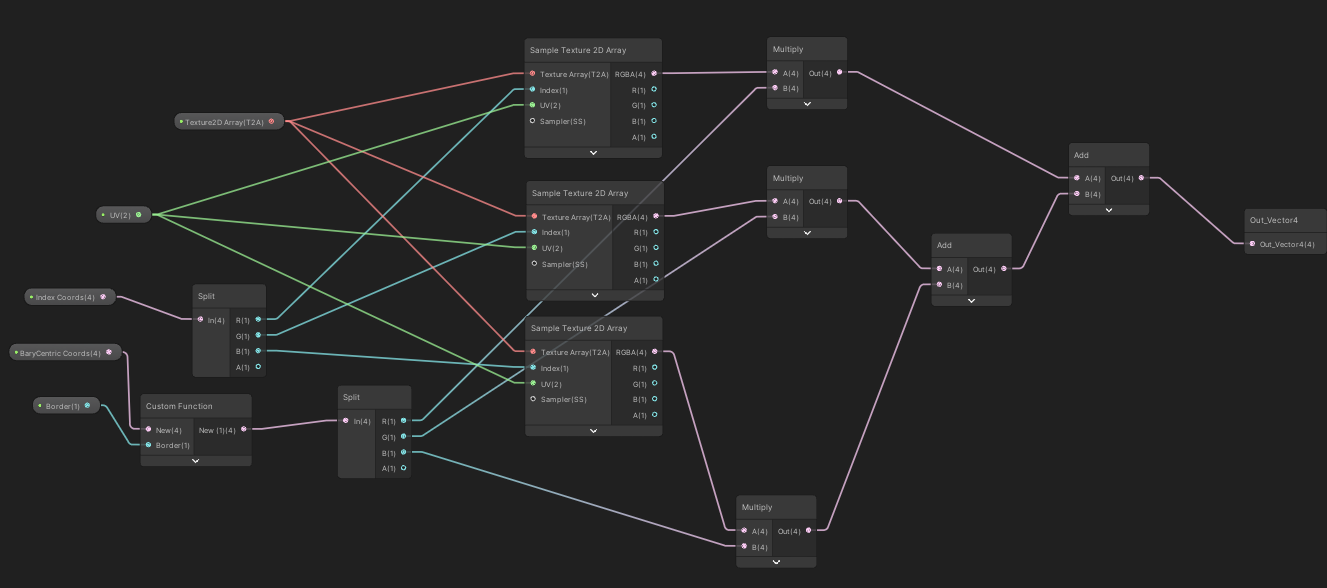
I have implemented the shader using unity shader graph.
I am not mapping actual uv coordinates in my marching cubes algorithm. Instead I use a triplanar mapping in the shader to get texture uv coordinates. Explaining how to generate a triplanar mapping or how to extrapolate normals is not part of this post.
However, for every triangle generated I allocate two custom sets of vector4 (uv) coordinates as input for my shader:
The First vector4 (uv0 in the shader) is the same for every triangle point and contains:
By keeping these vectors constant (x, y, z) for each point in the triangle I am certain that any shader texture point lookup for the triangle (which interpolates) has x as voxel type 1, y as voxel type 2 and z as voxel type 3.
I use a texture2DArray to get the texture needed, where x, y, z are indices in that texture 2D array.
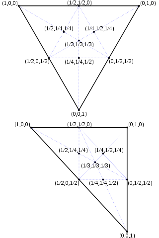
The Second uv vector (uv1 in the shader) will store the barycentric coordinates for each of the three triangle points.
When the shader runs, every point on the triangle gets extrapolated by mixing these 3 coordinates. They are the accurate barycentric coordinates of the actual point. Remember that the sum of the components x, y and z equals 1 (see also earlier screenshot). So each component (x, y and z) lies between 0 and 1.
And the closer a component is to the point, which represents a full voxel, the closer to 1 it gets so the more weight should be given to that specific texture.
We also know, for every point, what texture to use, thanks to the first uv vector. Simply multiply the output of the texture sample with the component value (x with the texture value of the first point, y with the texture value of the second point, etc). Then add the values together, and you have a blended texture.
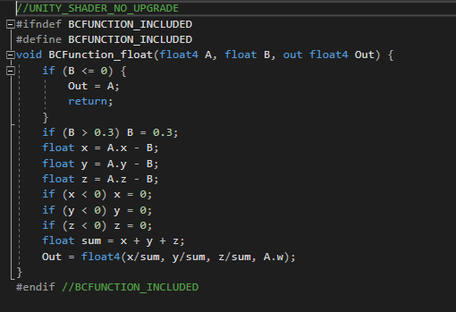
To create a bit of an offset for the blend, this function will help:
Personally I have settled on a border of 0.1.